How Does Metal 3D Printing Work: A Guide for Beginners
You might have come across the term Metal 3D Printing lately, and wondered how it works?
Well, it is the process by which components are manufactured by adding layers of metal on top of one another. 3D printing, in general, is a revolutionary technology which uses just the 3D CAD data of a component to create the physical component layer by layer.
Depending on the application, different materials such as thermoplastics, wax, sand and metal can be chosen as the raw material for 3d printing.
3D printing of metals is a complex process compared to other materials as it involves advanced machines and higher temperatures. Components impossible to be manufactured through other methods such as machining and casting, can now be easily manufactured through Metal 3D printing.
Although still in the nascent stage, Metal 3D printing has found a niche foothold in the manufacturing of components for the Aerospace, Automotive, Tooling and Medical industries.
There are a number of techniques through which metal can be 3D printed. Although fundamentally all the techniques add layers of metal, they differ in the way how each layer is printed and how the bonding is achieved. When planning to manufacture a part through Metal 3D printing, it becomes very important to have knowledge of each metal printing technique to understand it’s advantages and limitations.
Without further ado, let’s dive right into each metal 3d printing technique to understand how it works.
Direct Metal Laser Sintering (DMLS)
Metal 3D printing using laser to melt a bed of uniformly laid powder is the most common and widely used technique. This process is known by different names such as Laser Powder Bed Fusion(LPBF), Selective Laser Melting(SLM), Direct Metal Printing(DMP) and Direct Metal Laser Melting(DMLM).
The 3D CAD model is imported onto a data preparation software where the necessary support structures are provided and the entire model is sliced into number of layers. These slices have specific thickness ranging from 20microns to 100 microns and provide the necessary data for printing each layer.
Prior to printing, the whole build chamber is flooded with inert gas(argon/nitrogen) to minimize oxidation at elevated temperatures. Laser selectively melts the layer of metal powder which is uniformly spread on the build platform, thereby solidifying the melted powder instantly. Once this is done, the build platform moves down by a layer thickness and a new layer of powder is spread. Laser again prints this new layer during which the new layers bonds to the previous layer. The build platform again goes down and this process keeps repeating until the final layer is printed.
Post printing, the part is unloaded and depowdered to remove any trapped powder. The part undergoes heat treatment for improvement of mechanical properties. The part is then cut off from the build platform and the supports are removed. If required, machining is carried out to improve the dimensional tolerances.
Finally, the surface finish is improved by using methods such as vibro tumbling and shot blasting.
Advantages: High Repeatability with better dimensional tolerances and mechanical strength, Manufacturability of highly complex designs, Wide array of alloys to choose from.
Limitations: Limitation on the build volumes(size constraint), Relatively high cost per part compared to other metal printing processes.
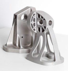
A part manufactured through DMLS
Photo credits: EOS Gmbh
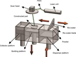
Working of DMLS
Photo credits: ScienceDirect
Electron Beam Melting (EBM)
Electron Beam Melting is similar to DMLS as both are powder bed processes, but differs in the source used to melt powder.
EBM uses an electron beam of around 6kW to melt the powder bed. Also, the powder particles are much bigger in size compared to DMLS powder. The printing data is prepared by slicing the 3D Cad model along with supports into numerous layers. The slicing is done with a much higher layer thickness compared to that of DMLS.
The build chamber is closed and vacuum is created in the entire build chamber to minimize oxidation. A layer of powder is spread on the build platform and the Electron Beam first heats the entire powder bed to an optimal temperature and then selectively melts the metal powder.
The build plate is then lowered to make way for a fresh layer of recoated powder. The beam again heats the entire bed and then selectively melts the new layer of powder, thus creating a bond with the previous layer. The build platform again goes down and this process keeps repeating until the final layer is printed.
As the powder bed is heated every layer, the entire build is maintained at around 1000ºC helping in reduced support structures and elimination of residual stresses.
Parts printed with EBM usually do not require any post heat treatment. The part is then cut off from the build platform and supports are removed. Machining can be carried out if required. The surface finish of parts can be improved with further post-processing.
Advantages: Lesser support structures due to elimination of residual stresses, Faster process compared to DMLS, vertical part stacking is easier.
Limitations: Limitation on the build volumes(size constraint), Relatively high cost, Limited material range, Poor surface finish and dimensional tolerances(+/- 0.2mm)
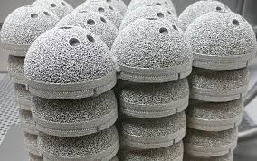
Parts manufactured through EBM
Photo credits: GE
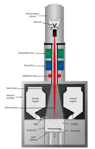
Working of EBM
Photo Credits: ARCAM
Binder Jetting
While plastic binder jetting is a proven method, binder jetting in metal is a relatively new technique compared to DMLS and EBM.
The process uses a binding agent to bond metal particles together layer by layer. Since the parts undergo sintering after 3D printing, there is massive shrinkage in the size of final parts. The CAD model to be printed is to be compensated for this shrinkage factor during the data preparation stage. The CAD data is sliced with a layer thickness of around 50 microns.
A recoater uniformly spreads metal powder on the build platform. The inkjet head having numerous tiny nozzles selectively deposits droplets of a binding agent over the metal powder. The binding agent containing wax and polymer, fills in the void between the metal particles, thus creating a bond. Once this is done, the build platform moves downward by a layer thickness and the process is repeated until the final layer is printed. The printed part is in a fragile green state and needs further post-processing to strengthen the part.
Infiltration and Sintering are the two methods used to strengthen the green state parts.
In Infiltration, the green state parts are washed to remove the binding material resulting in a metal part with internal voids. The part is then heated in an oven where bronze is used to fill up the voids creating a bi-metallic part. A density of around 95% can be achieved through infiltration.
In sintering, the green state parts are heated in a furnace for 24 hours during which the binding material is completely burnt away allowing the remaining metal particles to sinter together. Parts undergo shrinkage but achieve a density of 98%.
Advantages: Optimum for batch production due to lower production cost, no support structures required.
Limitations: Lower mechanical strength compared to DMLS, Limited range of materials, Non-homogeneous shrinkage makes it mandatory to run trails before production.
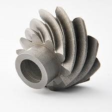
A part manufactured through Metal Binder Jetting
Photo credits: ExOne
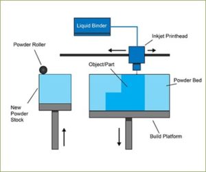
Working of Metal Binder Jetting
Photo credits: Loughborough University
Metal Material Extrusion
The working principle of Metal Material Extrusion is the exact same of Fused Deposition Modeling(FDM), raw material being the only difference between the two.
While FDM uses plastic as the raw material, Metal Material Extrusion uses a metal powder filled thermoplastic media as the raw material. The 3D Cad model with supports is sliced into numerous layers, and these slices contain the data for printing.
The raw material in the form of wire is made to pass through a nozzle. A heating element is present just before the nozzle to soften the material helping in easier deposition. The nozzle moves along the x and y axes to deposit heated material on the build plate. After printing a layer, the build platform goes down by a layer thickness and the nozzle again deposits materials as per the details of the next layer. This repeats until the final layer is printed. Ceramic media is printed in between the support and the part for easier support removal during post-processing.
Once the part is printed, it is heated in a furnace for debinding and sintering. Debinding removes plastic from the part and leaves behind only metal. Sintering covers up the pores and increases the density of the material.
The ceramic media disintegrates thus separating the support material from the part. The resulting part is shrunk by 20% and the final relative part density is around 96%.
Advantages: Low cost, Best for prototypes
Disadvantages: Porosity issues, Part Shrinkage might affect dimensions, Poor Surface Finish
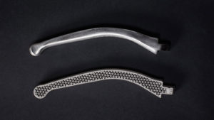
Parts manufactured through Metal Material Extrusion Photo credits: Markforged
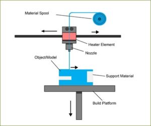
Working of Metal Material Extrusion
Photo credits:
Loughborough University
Direct Energy Deposition
Direct Energy Deposition uses either metal powder or wire as the raw material and laser beam or electron beam as the melting source for printing metal layer by layer.
Unlike Powder Bed Fusion which melts the predeposited material, DED melts the material as it is being deposited. Although the process can be used to manufacture new components, it is best suited for repairing damaged or worn out parts. It goes by different names such as Laser Cladding, Laser Metal Deposition, Laser Engineered Net Shaping and Electron Beam Additive Manufacturing.
The 3D Cad model to be printed is sliced into number of layers having specific thickness(starting from 100 microns) and these slice data provides the necessary input for printing each layer.
The powder or wire is pushed through a nozzle and is melted by the laser/electron beam depending on the machine. The melting source (laser/electron beam) is shielded by inert gas to prevent oxidation in case of an open system, and in a closed system, the entire chamber is flooded with inert gas. The energy source melts the material as it is being deposited. Once the first layer is printed, the head containing the nozzle and energy source moves upwards to print the next layer and the process is repeated until the final layer is built.
The printed parts will require heat treatment and optional machining depending on the application.
Advantages: Excellent choice for repairing parts, up to 6m length parts can be printed, high printing speed of up to 10kg of metal/hour, less material wastage, multi-material capability, hybrid manufacturing capability
Disadvantages: Low tolerances achieved, poor surface finish, cannot produce highly complex shapes, no support structures can be printed, very high cost
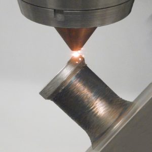
A part manufactured using DED
Photo credits: BEAM
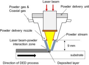
Working of DED
Photo credits: Science Direct
Ultrasonic Additive Manufacturing
Ultrasonic Additive Manufacturing is a solid-state technology for joining metal foils near room temperature.
While the metal foils are under a constant force, ultrasonic vibrations are applied to cause scrubbing of mating surfaces. Since the bonding temperature is significantly below the melting temperature, no change in grain size nor phase changes occurs.
Similar as well as dissimilar metal can be joined together with very minimal to no intermetallic compound formation resulting in a solid-state atomic bond. The properties of the final part are same as that of the raw metal foils.
This additive method is best used as a hybrid manufacturing method on a CNC milling machine. The printing head is mounted onto the milling machine and can be accessed as a simple tool change. Both printing and milling are carried out alternatively to achieve finer tolerances.
Once a layer of sheet is welded to the previous layer, a cutting tool machines the layer to achieve the final shape. The printer head moves up by the thickness of the metal foil and again welds a new layer of metal foil to the previous layer. This process is repeated until the final layer is printed. Parts might need further heat treatment depending on the application.
Advantages: Hybrid manufacturing capability, large parts manufacturing, dissimilar material bonding.
Disadvantages: Cannot create very complex shapes, has to be used along with machining.
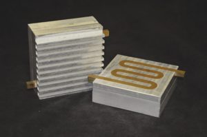
Parts manufactured through Ultrasonic Additive Manufacturing
Photo credits: Fabrisonic
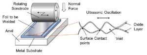
Mechanism of Ultrasonic Additive Manufacturing
Photo credits: ResearchGate
Conclusion
Although all the above technologies can print wonderful metal parts, continuous research is being carried out to develop new materials and qualify them for industrial applications. Efforts are being made to print parts much faster with very little or no post-processing. In the present scenario, Direct Metal Laser Sintering is the most widely accepted metal 3d printing technology due to the repeatability of quality parts ensuring parts with strength comparable to that of wrought parts.
There are 25 comments on this post
Great content! Super high-quality! Keep it up! :)
Great Article on metal 3D printing. Thanks for sharing .
There is certainly a great deal to learn about this topic. I love all of the points you have made. Dannie Niels Andres
I am so happy I found your blog and I absolutely love your information about how does metal 3d printing work and the tips you have shared are awesome. I liked and it is wonderful to know about so many things that are useful for all of us! Thanks a lot for this amazing blog!!
For most recent news you have to pay a quick visit world wide web and on internet I found this website as a most excellent site for newest updates. Jessica Saundra Bergmann
You completed various fine points there. I did a search on the theme and found a good number of folks will go along with with your blog. Hetty Sax Jenny
I think everything published made a great deal of sense. Del Alasteir Australia
Asking questions are really fastidious thing if you are not understanding anything fully, but this post presents nice understanding even. Vivienne Holly Siblee
After I originally left a comment I appear to have clicked the -Notify me when new comments are added- checkbox and now every time a comment is added I receive four emails with the exact same comment. Perhaps there is a way you can remove me from that service? Thanks a lot! Else Land Balfour
I have been absent for some time, but now I remember why I used to love this blog. Thanks , I will try and check back more often. How frequently you update your website? Holli Thayne Ash
I dugg some of you post as I cogitated they were handy invaluable Poppy Dimitry Arnoldo
Good post. I learn something totally new and challenging on websites I stumbleupon on a daily basis. It will always be exciting to read through articles from other writers and use a little something from other websites. Avis Lay Joshia
Thanks for finally talking about > How Does Metal 3D Printing
Work: A Guide for Beginners < Liked it!
my blog :: CBD for sale
It is really a great and useful piece of information. I
am satisfied that you just shared this helpful information with us.
Please stay us up to date like this. Thank you for sharing.
Here is my blog ... CBD oil for dogs
I like the valuable info you provide to your articles.
I'll bookmark your blog and check once more here frequently.
I am relatively sure I'll be told plenty of new stuff right right here!
Good luck for the next!
Here is my blog cbd oil for sleep
Its like you learn my thoughts! You seem to understand so much approximately this, such as you wrote the book in it or something.
I think that you simply can do with some % to force the message home a little bit, however
other than that, this is wonderful blog. A fantastic read.
I'll definitely be back.
This is a topic that is near to my heart... Many
thanks! Exactly where are your contact details though?
Our contact details are available on our website www.rapiddmls.com
Spot on with this write-up, I truly feel this amazing site needs far more attention.
I'll probably be returning to see more, thanks for the info!
Hi there friends, good piece of writing and nice arguments commented here, I am genuinely enjoying by these.
These are truly enormous ideas in about blogging. You have touched some nice
things here. Any way keep up wrinting.
It is perfect time to make some plans for the future and it's time
to be happy. I've read this post and if I could I wish to
suggest you few interesting things or tips. Maybe you
can write next articles referring to this article.
I wish to read even more things about it!